Patrick van Bergen
First published: July 30, 2004
Last updated: October 14, 2004
(Added Time-Frames)
Last updated: August 13, 2006
(Added stateful transitions)
On implementing a Finite State Machine framework
A few years ago I was asked to create a complex software agent. I didn't have any time to research what would be the best architecture for this agent, so I just made a quick design based on my previous experiences and went for it. For all intents and purposes, the design was actually not even that bad. But after a year it started showing some cracks.
The design consisted of separate modules communicating through messages. To exchange large data structures, these modules used common datastructures I called blackboards. Since the modules would change their behaviour based on the messages they received, they had simple state machines consisting of a state-variable and the characteristic switch statement. One module even contained what I now know is a hierarchical state machine: one of its states contained another (identical) state machine.
The design was good in that the functionality of the system was cleanly separated into different modules. So even though the agent could perform complex behaviours it was not hard to understand how it performed these. The problems arose in the hierarchical state machine and in synchronisation. A single layer in the hierarchical state machine consisted of about 10 states and about 15 state transitions. The state transition tests were scattered across the module even though I made some efforts to combine them. My colleague who was working together with me on this project also tended to add extra variables which also contained part of the state. I would then 'correct' him by creating more states in stead. We had a hard time keeping the whole thing from turning into a formless blob.
The other problem which crept into the system time and again, was synchronisation. Because sending a message takes a 'cycle' and some messages reached certain modules only via other modules, one module might think the system was still in phase X while the other module is already convinced the system is in phase Y. To solve these problems we had change code or even rearrange entire modules. It also left us wondering when the next synchronisation problem might rear its ugly head.
To be able to tackle these kinds of designs in a more relaxed way the next time around, I started studying common software architectures. At that point I had not even heard of this level of software development. Soon I encountered Finite State Machines again, this time not as a small tool inside a software module, but as a way of organising the entire system. I got very excited about it because it had all the properties I had needed in my agent design, and more.
The goal of this project is to create an FSM software library or framework that can be used to build software architectures for entire applications. The applications for which this architecture is especially suited are games and simulators. Since the FSM is pulling the entire application, it should allow for 1000's of states and transitions and bring in minimum overhead costs.
Luckily, we don't need to search far to find the specifications for a finite state machine. The UML has a very elaborate specification of so calledstatechart diagrams, the notational form in which Finite State Machines are expressed.
These are the characteristics of a fully formed Finite State machine. I will use UML's notation. At this point I would like to point out that I don't intend to give a literal implementation of UML's statecharts. I will only use those elements of UML's statecharts that I think are useful for our goal. If you want to learn the full UML notation, see the UML specification (chapter 3, section on statecharts).
General characteristics
- An FSM contains states and (state) transitions. A state defines the system's current behaviour. A transition defines a possible change to a different state. The state where the transition starts is called the source state of the transition; a transition's end state is called a target state.

The target state becomes active when a transition fires. At that point the source state becomes inactive. - A transition fires when its source state(s) is (are) active, and an event occurs.
- When a transition fires the exit code of the source state(s) is executed, followed by the transition code and the entry code of the target state. This code contains actions.
State characteristics
- A state may contain substates. These are states within states. A state containing other states is called the super state or parent state of these substates.

- A state may be an initial state. If a state is defined as initial state, it automatically becomes active if its super state becomes active.
- A state may be a final state. If a state is defined as final state, its superstate automatically becomes inactive when this state is activated.
- A state may have history, which means that it remembers the state of activity of all its substates, even when it is no longer active. When it is reactivated, the activity pattern of all substates is restored automatically. A shallow history restricts itself to a single level of substates. A deep history also affects the subsubstates and so forth.
- You can make specializations of states. Such a specialization may have different transitions from the generic state.
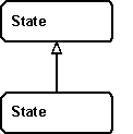
- A state may contain entry and exit code. This code is executed when the state is entered or left, respectively.
Transition characteristics
- A transition may contain an action. This action is executed when the transition fires.
- A transition may be an internal state transition. In that case the action of the transtion is executed, but the state is not left or reentered. No exit or entry code is executed.
- A transition may fire when a specific event occurs.
- A transition may have a guard condition that must be satisfied, or the transition cannot fire.
- A transition may be an automatic transition that fires upon completion of the actions within the source state.
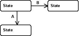
- Transitions have priorities. If several transitions can fire at the same time, it should be explicit which transition take precedence and which transition fires later or not at all. There are two special cases that need to be explicitly handled.
In the first case (see example image below) transitions A and B may become eligible to get fired at the same time. When that happens, only one transition may fire, not both. A priority should make clear which transition wins.
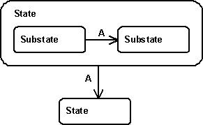
In the second case there is an inner transition that may fire, and an outer transition as well. There are two real possibilities. The first: the inner transition fires, followed by the outer transition. The second: only the outer transition fires. The inner transition is ignored. Later I explain why I choose the latter.
- Transitions may fire after some predefined time. When the source state is active for X seconds, the transition fires.
- Transitions may be complex transitions, it may have more than one source state and more than one target state. A transition with many target states splits control (forks) when it fires. All target states become active.

A transition with many source states synchronizes control (joins) when it fires. It can only fire if all source states are active.

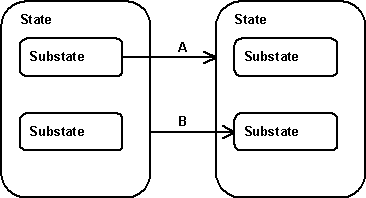
- Transitions may break through the boundary of their superstate (see A). If that is the case, the exit code of the substate must be executed, followed by the exit code of the superstate. In the same vein, the transition may end in a substate (see B). If that is the case, the entry code of the super state is first executed, followed by the entry code of the substate. Deeper states of nesting are also supported, of course.
- Transitions may be stack-based, that means that a state should have the possibility to revert to its previous state, the state it was in before the last transition fired. If a state can be reached via several transitions, you may want to have the possibility to return to the previous state. This is not available in the UML.
Event characteristics
- Signals are events that can be broadcast by both states and transitions. This is the common form of transitions.
- Call events are just procedure calls. State 1 calls a procedure in state 2. This is an odd duck in the UML spec. I don't support them.
- Time events occur when some span of time has elapsed. Use it to create transitions that should fire when the FSM has spent some time T in some state S.
- Change events occur when some property has changed into a specified value. The propery may also be time, i.e. at 10:00.
Action characteristics
- An action may execute any application code.
- An action may defer an event. This means that the event is stored for later processing.
- An action may broadcast a signal to all active states.
When I tried to implement the FSM framework I stumbled over some issues, which I will describe here.
Stack-based state machines
Computer science has created a state machine that uses a systemwide stack as its most important datastructure. Its called a pushdown automaton and is used to recognize context-free languages. At the one hand such an architecture would be very different from the one we're developing here. On the other hand, it would be very nice to have these stack properties.
The stack-based properties we would like to have come down to the following. A state should be able to remember via which transition it was reached (we call this push). And it should be able to reverse this transition to go back to its previous state(s) (pop).
I mention this issue under "pitfalls" because I did not come across stack-based state machines via the normal computer science way, but because I read about them in AI Game programming wisdom 2. For a long time I thought it was just an extension to the FSM architecture I was thinking about. Only later I acknowledged that it dealt with an entirely different architecture. Stacks are used, apparently, to create a state hierarchy in a different way than we use in this article. It is an interesting concept, but it is not compatible with concurrency, at least not with a single system-wide stack. This also means that I (a.f.a.i.k.) "invented" the concept of push- and pop-transitions I will mention later.
Time Frames
A state machine that parses a sentence or solves a problem should run as fast as possible, cycle after cycle, without delay, until it's finished. A state machine for a game character may not be so arrogant, however. It gets a predefined slice of processor time, called a time-frame. A typical game or simulation updates all its components 50 or 100 times per second. Every component gets only a part of this 1/100th second. The AI of a game may get 1/10th of the time of 0.01 second, which equals 0.001 second. This is the time-frame of the AI. If the time-frame is violated too much, the game may show a visible delay or the physics engine may get confused.
A simple but naive way to deal with this is to run a single cycle of each component in each time frame. This doesn't work for a state machine, at least not when your application requires multiple transitions to be fired sequentially in a short period of time. A cycle per time frame means that only 100 cycles may be performed sequentially in a second. Often, a long time of inactivity is followed by a burst of state changes that should occur (almost) instantaneously.
A better way is to allow your state machine to perform cycles until the time-frame is finished. This idea is closely related to the timeline synchronizer of the structural model architecture. A time-frame needs not spend all of its time performing cycles. It is possible to predict if any transitions are likely to occur in the rest of the time-frame. If no transitions are likely to occur, you can stop the time-frame, or if your application requires time-frames to have a fixed duration, to burn the rest of the time-frame, which means call a Thread::Sleep() or such.
Implementing a complex FSM framework is not easy. I will handle the most important design decisions here.
Functional or Object oriented
Simple FSMs containing only a few states, have no hierarchy and no entry/exit code can be easily implemented using a switch statement and a number of functions for all code. However, object oriented design comes natural to complex FSM's. Keeping track of the transitions connecting to a state, the entry and exit methods that belong to it, the list of substates are all much more naturally implemented using OOP.
In an earlier implementation I chose to write all state code as methods of a central Model class. For example, I had a CFSMModel::Exit(CFSMState *State) method that had to be overridden by the application. This method was called when any state was entered. The method should use a switch statement to determine what code to execute for the State. The rationality behind this choice was then that it was less work to program, because you would not need to define so many classes (one for each state). The reason I left this design is of course that the FSM should accomodate 1000's of states and the design would imply that the FSM would be switching all the time. What's more, designing a complex system would be a nightmare because the functionality could not be split up in functional modules.
Control flow
An important implementation decision concerns the control flow of the FSM.
At first sight a control flow using a separate thread for every active state may seem like a good idea. It is a good idea if we only consider the ongoing activity in the active states. However, the FSMs we like to build contain 1000's of states and frequent state transitions. The idea of starting and stopping threads at that rate and the accompanying taskswitches will surely bring the system to a crawl.
Another control flow would also seem to be a likely candidate: event based. That means that the architecture should have some sort of bus mechanism on which all elements of the FSM may post messages (signals) and which will then asynchronously deliver these messages to their destination states. Transitions waiting for a signal could subscribe to these kinds of messages. The problem here is that is perfect for signal-based transitions but that it does nothing for other types of transitions. They would need another mechanism. Nevertheless, this control flow has become an important part of my architecture.
The final distinction which profoundly influences the architecture is the choice for push or pull (or polling). At first I adopted a pull scheme, that means that at every cycle, the model checked all transitions that started in the active states to see if they should fire. All transitions 'pulled' data from the world to see if they should fire. The advantage was that it was easy to model complicated transition-criteria and to model that states close to the root state should be checked first. This scheme stays close to the simple implementation of a statemachine using the double switch-statement.
I dropped this scheme when I used the framework for an application that stayed in a waiting state for a long time, doing nothing functionally. The model however was pretty busy, constantly checking all active transitions.
I rebuild the framework into a push scheme. Whenever a transition becomes active (when all its source states are active), it registers itself with the model and becomes idle. Transitions that do not need to fire stay completely inactive. Only when the model picks up a signal or finds out the timer of the transition times out, it notifies the observing transition and tells it to fire. This greatly reduces the time overhead of the framework, especially for state machines with many infrequent transitions.
Every update cycle now consists of two phases:
- A list is made of all transition that are eligible to be fired. Whether a transition should fire depends on the type of transition. A time transition keeps a timer with the model which times out after a number of seconds. An automatic transition is always added to the list. A signal transition is added to the list if the signal has occurred. The list is kept ordered, first by level, than by priority. Transitions closer to the root (lower level) are fired before transitions lower down (higher level). Transitions with equal level may be prioritized explicitly with an Priority value. The signals are then thrown away.
- The transitions of the list are fired from first to last. Transitions closer to the root are thus fired first. Transitions within the same level are fired in the order specified by their priority. When a transition fires, it may deactivate transitions later in the list. These firings broadcast new signals, schedule new time transitions, etc. These will be processed in the following cycle.
Concurrency
As described in the Pitfalls section, I chose to allow multiple substates to be active at the same time. This makes the implementation easier because I did not have to define special types of states that would only serve as containers for concurrent substates. All states are alike in my implementation. They allow for multiple active substates.
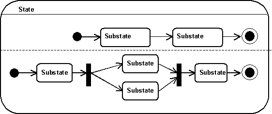
Even though concurrent substates are not explicitly implemented, the UML representation may be used to model them. As an example I present here a state with a 6 substates. All substates are direct substates of the state. The dashed line in the figure is not explicitly implemented. It just serves as a visual reminder that the processes it separates are concurrent.
Initial and final states
The black circles in the UML figure just above in the section on concurrency are not implemented as pseudo states in the UML sense, but as properties of the (sub)states they are attached to. The black circles denote that the state attached is an inital state, the concentric circle denotes a final state.
History
A state's history is not implemented as a pseudostate, but as a property of a state.
A state may have no history, shallow history (only the activation of the substates is stored when the state is deactivated) or deep history (the activation of all substates is stored, recursively). In my current implementation the states are told recursively about their history. Setting a states' history to 'deep' will set the history property of the state and its substates, recursively, to true. Earlier I used a more direct implementation of the history property, using values 'none', 'shallow', 'deep' and 'inherited'. Evaluating these during an activation proved to be cumbersome and would take more time than I'd like.
Transitions, complex transitions, self transitions, internal state transitions, update transitions, and stack-based transitions
It was possible to implement all transition functionality in a single class. This class represents a complex transition with multiple source and target states. The simple transition with a single source and target state is simply a special case of this complex transition.
Transitions have another property that needs to be implemented. I added a picture to illustrate it. A transition between two substates A1 and A2 usually goes directly via T1. However, it is also possible that you want to execute the exit and entry code of their superstate A as well. This can easily be done by creating a transition T2. I implemented this by forcing the developer to add transitions to the FSM via states. The state, which I called the spanning state determines the height to which a transition "rises" before lowering to the target state. For example, T1 was added to the FSM via state A; it has no need to rise above A's state boundary. T2 was added to the FSM via state B; it rises above A's state boundary, but does not leave B's state boundary.
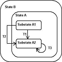
Transitions from one state to itself (self-transitions) can also be modelled. T3 in the picture connects A2 with A2. When it fires it deactivates A2, executes its exit code. After that is activates A2 again, executing its entry code. T3 is added via state A. If it were added via state B, it would also execute A's exit and entry code.
Internal state transitions may be modelled by defining the transition from the state to itself and adding it to the state itself. An internal state transition does not call exit or entry code. It doesn't even deactivate and activate the state. It only executes the transition code.
As mentioned in the pitfalls section on updates I added a special update transition. This internal state transition fires every time the state is active for some specified duration. At that time it calls the virtual function Update() on the state, deactivates and reactivates the state. The Update() method contains the code that should be executed on a regular basis while the state is active.
Stack-based transitions, as mentioned in this section consist of push and a pop transitions. Many push transitions may lead to some state S, as shown in picture 1 below. All these transitions (Push1 and Push2) are connected to a single pop transition (Pop). When a push transition (Push2 in the example) fires, the pop transition is notified. It pushes a pointer to the push transition on its stack (see picture 2). The state S then becomes active. When the pop transition fires, it pops the last transition off of its stack, takes the source states of this transition and makes them its own target states.
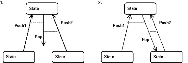
The reason why the pop transition uses a stack in stead of a single memory position is that these stack-based transitions may accumulate. More importantly, a push transition P may fire for a second time, before the connected pop transition has fired. Therefore pop transition need to keep track which push transitions it has popped, and which ones are still on its stack.
Developer note: if the stack of the pop transitions should be cleared when some superstate of the pop transition is deactivated, the application is responsible for calling the Reset() function on the pop transition.
Transition levels and priorities
The order in which the transitions are fired within a cycle may not be random. It should be well defined. Transitions can be of different levels and may have different priorities. If two transitions are ready to fire, the one with the lower level is fired first. This may cause the other transition to become deactivated; if so it will not be fired. If two transitions have the same level, the one with the higher priority is fired first. Again, this may deactivate the other transition.
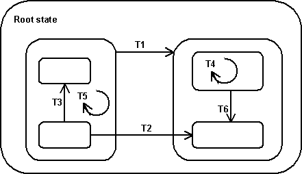
The level of a transition equals the level of its spanning state. The spanning state is the state to which the transition is added. It is the smallest state that contains all source and target states of the transition. It's a concept that becomes important if you're using the state machine in advanced ways, so I'll give some examples.
- In the figure above T1 and T2 are on the same level. Since their spanning state is the root state of the state machine, the level of these transitions is 0.
- T3, T5, and T6 are level 1 transitions. T4 is a level 2 transition.
- If T1 and T2 are both ready to fire, the one with the highest priority is fired first.
- T4 and T5 are internal state transitions that do not deactivate their source state. Their source states equals their target state which is also their spanning state.
- It is also possible that both T3 (an internal state transition) and T5 can fire at the same time. At this point the priority of these transitions is taken into account. The transition with the higher transition fires first. And since this doesn't deactivate the other transition, that one will be fired next.
- If both T1 and T3 are ready to fire, T1 is fired. This deactivates its source states and this deactivates T3. Therefore T3 is not fired. Why not fire T3 first and fire T1 right after that? That would make sense. The reason should become clear by taking T2 and T3 as another example. The transitions are comparable to the ones in the first example. However, if we now fire the higher level transition (T3) first, it deactivates the lower level T2! This is undesirable behaviour, because T2 is more important than T3. It's effect on the application's state is greater. To prevent this and to be consistent, I use the scheme of firing lower levels first.
Signals
You create a signal(type) by instantiating the CFSMSignal class or a self-made subclass. When you add the signal to the state machine model, you receive a signal-identifier. Use this identifier in transitions and broadcasts.
If your subclassed signal has parameters, you create a signal with different parameters by modifying the actual values of the parameters of the existing signal. Don't create a new object of your signal class, unless you want to introduce a new signal type entirely.
Signals can be used in two ways. Most signals are used throughout the state machine. I will refer to these as model signals. But it is also possible that the signal's scope should be a single state (and substates) only. This is the case when multiple instances of this state exist. My example is that of 100 agent-states, all using the same signals, but the signal of the first agent should never reach agent 2 or chaos will set in. These signals I will call state signals.
Model signals should be created in the constuctor of the model, and their id's are stored as class members. That way they can be reached from anywhere in the state machine. For example, broadcasting a machine signal goes thus:
State signals should be created in the constructor of the state that forms their scope. The id's of these signals are stored as class members. Everytime you create an instance of the state, all the state's signals are duplicated as well. They may have the same properties but they have different id's from the first signals. The outer state that creates the signal passes the id of the signal to the substates that use it, by passing the id as an extra constructor parameter. The substate stores the id for later use. The following code shows this:
int SignalWaitForItemTimedOutId;
public:
CFSMStateActive(CFSMModel *NewModel)
{
SignalWaitForItemTimedOutId = Model->AddSignal("wait for item timed out");
AddSubState("waiting", new CFSMStateWaitForScheduledItem(Model, SignalWaitForItemTimedOutId));
AddSubState("checking", new CFSMStateChecking(Model));
AddSignalTransition("waiting", "checking", SignalWaitForItemTimedOutId);
}
Time-frames and update strategies
In my model's Update() method, your preferred update strategy is executed. You can choose to perform a single cycle, perform cycles for the duration of a time-frame, perform cycles until it's no longer useful (no more transitions are expected in the rest of the time-frame), or do this and burn time for the remainder of the time-frame.
This section contains the solution I found to a problem I faced for about half a year. The problem can best be illustrated by a simple example: take a garage door. It can be open and it can be closed. These are two states. But it doesn't close immediately. While it closes it is in a third state: that of closing. It can be modelled simply by providing with three states and a couple of transitions. In this simple case, there is no need to say that there are really two states (open and closed) and a very odd transition that takes a lot of time (closing). But what about the stereo set I own? I start out playing a cassette. The lit covering the cassette player is open. At that time I can do many things; two among them are shutting down the stereo completely by pressing the 'on/off' button, and starting to play a CD, by pressing its play button. Both actions cause the lit covering the cassette player to close. Closing the lit seems to be part of the transition from one state to the other. But so far, transitions have been immediate; they have not taken any time. Since the closing of the lit takes time, it would have to be modelled as a separate state or group of states, and this series of states should be modelled twice: once for turning the stereo off, and once for starting to play the CD. And this to me seems awkward. It seems to me that closing the lit is part of the exit code of the cassette player. The major change of thinking about state machines I am suggesting here is to treat exit code, entry code, and transition code as states; and to create a temporary state machine chaining these states in the process of transition.
To make this clear, I created a picture showing the three types of code, or action states, as circles.
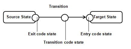
I am suggesting to create, at the time of transition firing, a single temporary superstate (or embedded FSM) that contains states for all exit, entry, and transitions, in the order that they are normally executed. These states would then be connected by temporary automatic transitions that will fire at once when a code state has completed. The source state from which the transition was fired, will be connected to the first action state by an automatic transition. The last action state will be connected to the target state by another automatic transition. All temporary transition should be action-less (they have no exit, entry, or transition actions), because if they had it would cause an infinite regress (endless loop). The code states themselves are not temporary, but they are action-less as well, for the same reason. (An action state is therefore a special kind of state that has no action states of itself.
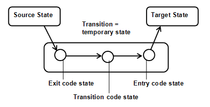
The temporary superstate is cleaned up (destroyed), when the first transition leaving the temporary superstate fires. At that point the superstate is destroyed, along with all the temporary transitions. The action states are all deactivated, but are not destroyed. They may keep their history.
Another strength of stateful transitions is that that they may be interrupted. Consider the example of an elevator door closing, a not-so-simple example of a system changing from one state (door open) to another (door closed). While the door is closing (something we can now interpret as a stateful transition), the elevator may receive a signal that someone or something is entering. At that point the closing sequence is terminated and replaced by a door-opening sequence. We can model this by allowing normal transitions between action states and normal states.
The following picture illustrates this; during the stateful transition a transition originating from one of the action states fires.
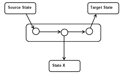
At that point the temporary superstate is broken down along with all temporary transitions. A new stateful transition is created between the action state the new state (State X). Note that the action state has no exit action state.
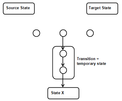
Remark: although the transition between "Source State" and "Target State" is not always drawn in these pictures, it is not removed, I just left it out to show that it does not play a role in this example.
Early state machines were "flat", containing only states and transitions. Two types of FSM were distinguised: Moore machines, that performed their function while in a state. And Mealy machines that performed their function through executing transition code, on firing transitions. Hierarchy and concurrency were introduced into the field by David Harel in 1987.
- Statecharts: A Visual Formalism for Complex Systems. David Harlan (1987)
The paper in which statecharts, featuring hierarchy, concurrency and communication, were introduced. - Unified Modeling Language (UML) specification
Chapter 3, UML Notation Guide, contains the specification of UML statecharts. - Thesis on Concurrent Hierarchical State Machines. Paul Jay Lucas (1993)
An object-oriented language system for implementing concurrent, hierarchical, finite state machines. The accompanying website. - Stack-Based Finite-State Machines. In: AI game programming wisdom 2. Paul Tozour (2004)
Very clear article on stack-based state machines. - On the Implementation of Finite State Machines. Jilles van Gurp & Jan Bosch (1999) Makes a stand against procedural implementations of state machines. Points out the shortcomings of the Design Pattern 'State'. Focuses on maintenance of FSMs.
- Practical Statecharts in C/C++: Quantum Programming for Embedded Systems. Miro Samek (2002)
Samek describes his Quantum Framework, a finite state machine framework fit for Real-Time Operating Systems. It uses Active Objects (hierarchical, but not concurrent, fsm's). All AO's reside in separate threads. They communicate via events. See also the accompanying website. - State-Oriented Programming. Miro Samek and Paul Montgomerey (2000)
Programming with state machines: a new programming paradigm!


